


- Home
- > Expert Insight
- > Conductor design
- > Conductor diameter: How to find the right balance between electrical and mechanical constraints?
Conductor diameter: How to find the right balance between electrical and mechanical constraints?
The choice of conductor diameter for overhead transmission lines is a complex engineering compromise. Of course, it is driven by the required aluminium section to carry the current. However, designers must also balance conflicting electrical requirements, primarily driven by the corona effect, against the structural and mechanical constraints imposed by wind loads and ice loads.
The corona effect: Pushing for larger diameters
The corona effect occurs when the surface field gradient on a high-voltage conductor exceeds the breakdown strength of the surrounding air, leading to localized electrical discharges. This phenomenon generates undesirable environmental consequences, most notably audible noise (AN), radio interference (RI), and corona power losses.
To mitigate these effects, the primary strategy is to reduce the electric field gradient at the surface of the conductor. This surface gradient naturally decreases as the conductor diameter increases.
A larger conductor diameter distributes the electrical charge over a wider surface area, thereby raising the corona inception voltage: the threshold at which corona discharges begin.
Relative air density also affects corona inception voltage. As air density decreases with altitude, corona effects can become more critical on high-altitude lines and may require specific attention during conductor and bundle design.
Inception Voltage vs Air Density
Gradient: 16
Gradient: 17
Gradient: 18
Gradient: 19
Gradient: 20
Gradient: 21
Gradient: 22
Graphic from CIGRE TB638
Consequently, minimizing environmental nuisances like audible noise and radio interference pushes line designers toward specifying larger conductor diameters.
Corona effects can also be mitigated by increasing the number of subconductors in a bundle. I will detail this aspect separately in a dedicated article on bundle design.
Wind loads and ice loads : Constraining the diameter
Conversely, increasing the conductor diameter introduces severe mechanical penalties, since the horizontal force exerted by wind pressure on an overhead line is directly proportional to the conductor’s outside diameter.
According to IEC 60826 the load on the conductor is given as:
Where:
- Ac: load in newtons N due to the effect of the wind pressure
- q0: dynamic reference wind pressure in Pa which is dependent on the reference wind speed and the roughness factor corresponding to the terrain.
- Cxc: drag coefficient of the conductor
- Gc: combined wind factor for the conductors which depends on conductor height and terrain categories.
- d: diameter of the conductor in (m)
- L is the wind span of the support, equal to half the sum of the length of adjacent spans of the support.
- Ω is the angle between the wind direction and the conductor.
A larger diameter captures more wind, transferring significantly higher mechanical loads to the attachment points, towers, and foundations. For instance, increasing the cross-sectional area (and thus the diameter) to manage electrical constraints might necessitate costly reinforcements of the tower structures. From a strict mechanical loading perspective, utilizing conductors with smaller diameters (or fewer subconductors in a bundle) is highly preferable to minimize tower strength requirements and reduce overall line costs.
Similarly, the absolute total weight of ice that accumulates per unit length of a conductor is directly proportional to its outside diameter. Larger diameter conductors will accumulate a heavier absolute mass of ice, which can generate enough vertical load to collapse tower crossarms.
Composite cores and aluminium wire profiles: design levers for conductor diameter
Conductors based on a single composite-core architecture can use a smaller core diameter than equivalent stranded steel-core designs, thanks to the low density and high tensile strength of the composite core. For example, an HVCRC Drake conductor uses a 9.53 mm carbon/glass fiber core, whereas an ACSR Drake conductor has a steel core made of seven 3.45 mm strands, resulting in an overall core diameter of 10.35 mm.
This reduction in core size can be used to decrease the overall conductor diameter.
In practice, however, most composite-core conductors retain a diameter similar to that of conventional conductors in order to maximize the aluminium cross-sectional area and thereby reduce electrical resistance.
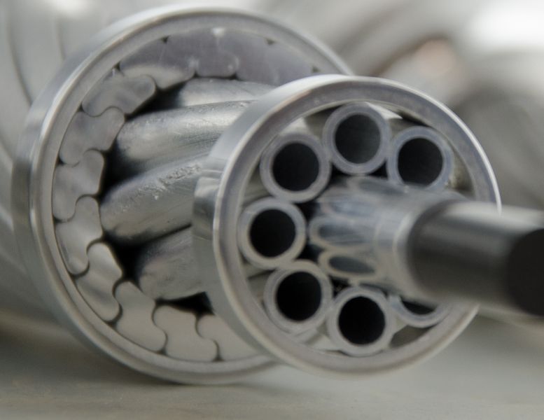
The shape of the aluminium wires also provides an effective means of optimizing conductor diameter:
- Trapezoidal and Z-shaped wires reduce the overall conductor diameter for a given aluminium cross-sectional area compared with conventional round wires.
- Tubular wires increase the conductor diameter without increasing the aluminium cross-sectional area or the associated weight.
More details about this conductor design on this page of Nexans website
The aerodynamic stability challenge (diameter-to-weight ratio)
However, attempting to resolve the corona issue by artificially expanding the conductor diameter without proportionally increasing its weight (to avoid overloading the towers vertically) leads to another mechanical hazard: aerodynamic instability. The “diameter-to-weight ratio” is a critical indicator of how a conductor will behave under wind pressure.
Field experiences demonstrate that lightweight, bulky conductors with high diameter-to-weight ratios (specifically those exceeding 23,000 mm²/kg) are highly susceptible to erratic movements in the wind. Instead of maintaining a steady, damped swung position under wind pressure, these conductors oscillate unpredictably. This erratic behavior drastically increases the “blow-out” (swing) and the risk of mid-span flashovers. To safely use conductors with such high ratios, engineers must implement mitigation techniques, such as adding weights to jumpers or increasing the clearances between the tower body and the conductors. Selecting the optimum conductor diameter is therefore not a matter of maximizing electrical performance alone. The conductor must be large enough to carry the required current and control the surface electric gradient, while remaining compact and dense enough to limit wind loading, ice loading, aerodynamic instability and structural reinforcement costs
Conclusion
Ultimately, selecting the optimum conductor diameter requires a careful balance: it must be large enough to carry the current and control the surface electrical gradient and limit corona-induced noise, yet small and dense enough to keep aerodynamic wind and ice loads and structural costs within safe, manageable limits.
CIGRE Technical Brochures (TB)
International Standards