


- Home
- > Expert Insight
- > Materials science
- > Materials science of advanced conductor cores: comparing steel, invar and composites
Materials science of advanced conductor cores: comparing steel, invar and composites
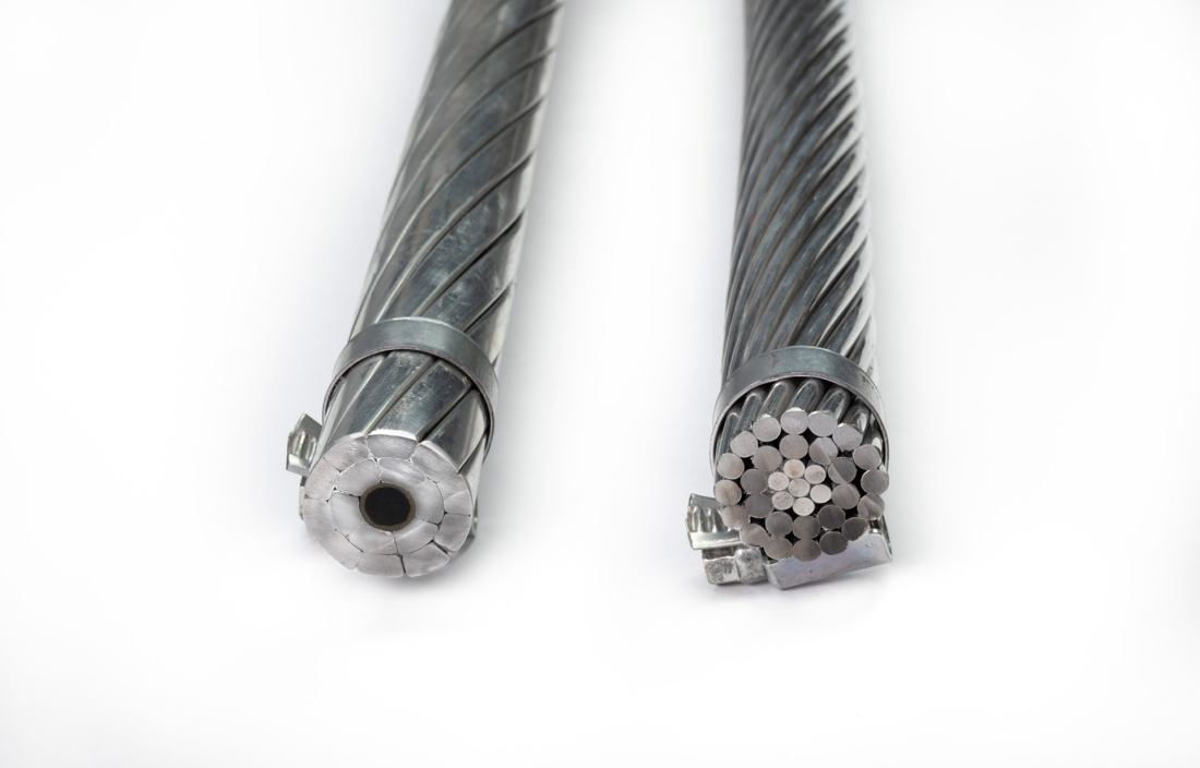
Overhead transmission lines are often discussed through conductor-level metrics: ampacity, sag, rated tensile strength, electrical resistance, thermal rating or installation constraints. These are the right indicators for line design.
However, the mechanical and physical properties of the conductor core explain why conductor technologies can behave so differently in operation.
In advanced conductors, the core largely defines mechanical strength, thermal expansion behavior, long-term sag response and installation robustness. The core also indirectly affects electrical performance, because it influences the conductor architecture and the amount or grade of aluminum that can be used.
In this article, we’ll compare the main families of conventional and HTLS conductor cores, to better understand their performance envelope.
The comparison will include all steel and composite conductor cores with a significant installed base, with data sourced from publicly available sources:
- Conventional steel cores used in ACSR, ACSS or Gap conductors (GTACSR / GZTACSR), from standard strength steel up to the highest grade of steel.
- Invar steel cores used in metallic HTLS conductors such as TACIR and ZTACIR
- Metal Matrix Composite cores (ACCR)
- Stranded carbon composite cores, such as ACFR
- Hybrid carbon-glass fiber composite rods (HVCRC® and ACCC)
- Extra-high-strength hybrid carbon-glass rods (HVCRC ULS and ACCC ULS)
- Full-carbon composite rods, such as those used in Lo-Sag conductors
The objective of this comparison is not to replace conductor design calculations. It is to show what can already be understood from the core material properties alone.
Let’s start with the fundamental material drivers behind conductor behavior:
- Tensile strength: the maximum stress the core material can withstand before failure. It indicates the mechanical strength of the core under tension.
- Elastic modulus: the material’s resistance to elastic elongation under load. A higher modulus means the core stretches less for a given tensile stress.
- Density: the mass of the core material per unit volume. A low-density core leaves more room for conductive aluminum within the conductor’s weight limit.
- Coefficient of Thermal Expansion (CTE): the extent to which the core material expands when temperature increases, creating unwanted sag at high operating temperatures.
Tensile strength & elastic modulus: “raw mechanical performance”
Tensile strength and elastic modulus are often used to evaluate “raw mechanical performance”.
Both are useful first indicators, but they do not have the same practical importance:
- Tensile strength directly defines the mechanical strength of the core, so it is a crucial parameter for all line designs.
- Elastic modulus affects elongation under load and can become important for specific line-design cases, especially long spans, high mechanical loading or heavy ice areas. However, it is not usually the main driver of conductor selection.
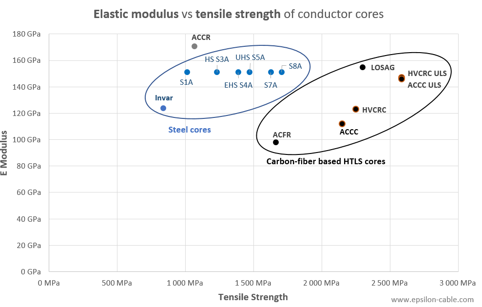
In a simple modulus comparison, steel performs well: all typical steel grades have an elastic modulus around 200 GPa. However, when accounting for the fill factor and lay ratio penalty, the equivalent stranded-core modulus values drop to 151 GPa, which is in the same range as Ultra Low Sag carbon fiber based composite cores and full carbon cores*.
On the other hand, with the same comparison methodology*, carbon fiber based composite cores generally offer significantly higher tensile strength than steel cores, which range between 1000 MPa for standard S1A steel cores, up to about 1500 MPa for S5A Ultra-high-strength steel cores, and around 1700 MPa for proprietary grades such as Bekaert’s S8A grade (marketed as “giga steel”).
- ACFR is the carbon fiber core technology with the lowest tensile strength, in part due to its stranded architecture, with manufacturer’s documentation showing a 16% strength penalty due to fibers not being aligned in the axial load direction. However, even with this relatively low tensile strength, it is on par with the strongest steel cores.
- All monolithic composite core technologies (ACCC, HVCRC and full carbon fiber cores) offer a much higher tensile strength than any steel core: more than double the strength of standard S1A steel, and more than 30% higher than the strongest grade of steel (S8A).
NB : ACCC, HVCRC and full carbon fiber cores have a similar tensile strength. HVCRC has a 5% higher tensile strength than ACCC due to a higher percentage of carbon fiber, and full carbon fiber cores have an additional ~2% additional strength as compared with HVCRC. - The extra-high-strength or “Ultra Low Sag” (ULS) versions of ACCC and HVCRC conductors, offer the highest tensile strength of all core options: more than 2.5 times the strength of standard steel cores, and more than 50% stronger than the best steel grade.
However, this raw comparison remains irrelevant if we don’t take into consideration that carbon fiber based composite cores also offer a much lower density.
Why specific performance drastically changes the comparison
The real-world difference between metallic and carbon fiber based composite cores becomes much clearer when we look at materials’ specific performance: strength-to-weight and stiffness-to-weight ratios.
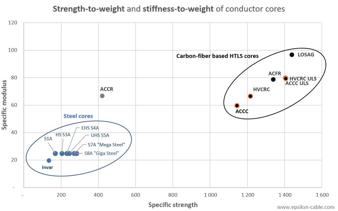
Steel cores have been gradually improved with higher-strength grades such as S7A and S8A, increasing tensile strength by up to 68% as compared with standard S1A / GA2 steel, with no improvement in the modulus of elasticity. However, the density of steel is unchanged, so the gain in specific strength from higher steel grades remains relatively marginal.
Carbon-based composite cores operate in a different range. Their density is more than 4 times lower than steel, while their tensile strength is higher. This gives them a much higher strength-to-weight ratio.
The same logic applies to specific stiffness: even if the absolute elastic modulus of steel remains high, its high density reduces its stiffness-to-weight ratio.
All carbon-based composite core technologies are therefore much more efficient when mechanical performance is considered per unit mass.
Since conductors are suspended structures, weight is a critical parameter. Lower core density helps reduce total conductor mass, structure loads and sag-related constraints. And this becomes even more critical when combined with low thermal expansion.
Lower core mass means more aluminum for the same conductor weight
The density advantage of composite cores is not only a material-property benefit. It can be directly converted into conductor design options. For example, replacing the steel core of an Drake-type conductor with an HVCRC composite core can reduce the core linear weight from about 512 g/m to about 132 g/m. The resulting difference, around 380 g/m, can be “reinvested” in conductive aluminum without increasing the total conductor weight.
This represents roughly 140 mm² of additional aluminum cross-section. Compared with the 403 mm² aluminum cross-section of a Drake conductor, this corresponds to approximately 35% more aluminum at iso-weight.
This is one of the main system-level advantages of low-density composite cores: the weight saved on the core can be used to either:
- reduce conductor weight
- reduce structure loads
- increase aluminum cross-section, to improve ampacity and reduce electrical losses.
Low thermal expansion: the decisive advantage of carbon fiber composite cores
The coefficient of thermal expansion is one of the most important properties for conductors, as it directly contributes to line sag at higher operating temperature.
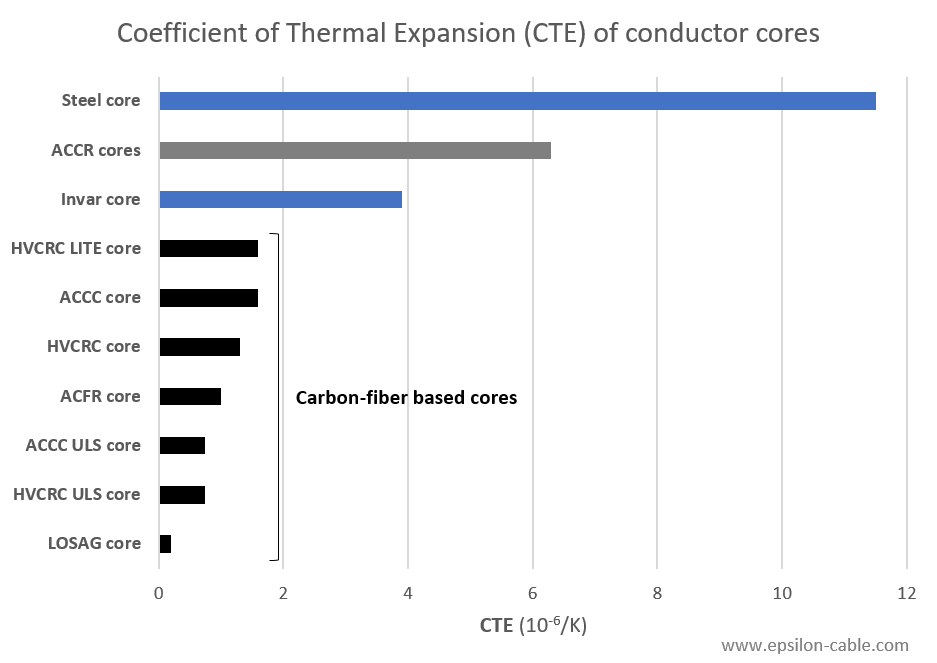
Steel cores typically have a coefficient of thermal expansion around 11.5 × 10⁻⁶/K. This means that the core expands significantly as temperature rises: from 20°C to 200°C, a steel core will expand by 0.21%. On a typical ACSS conductor, this will increase the initial sag by 4 to 6 m on a typical span of 300 to 400 m.
When the steel core wires are thicky clad in aluminum to improve corrosion resistance and conductivity (such as ACSR/AW or ACSS/AW), ), the overall CTE of the core increases to 13.0 × 10⁻⁶/K, further increasing thermal sag.
Invar cores (aluminum cladded Fe-Ni alloy) were introduced to address this limitation. Their coefficient of thermal expansion is typically in the 3 to 5 × 10⁻⁶/K range, which is two to four times lower than conventional steel. This makes them useful in low-sag metallic conductor designs. However, Invar remains a metallic solution, so its density is still high, and its elastic modulus is 20% lower than other steel cores. It improves one major weakness of steel, but it does not fundamentally change the overall material envelope.
Carbon fiber based composite cores go much further. All carbon-based technologies reach very low CTE values, typically far below steel and Invar. Full-carbon rods can even reach thermal expansion close to 0. In practice, this will translate in a minimal thermal conductor sag, often below 1 m, even for wide spans.
This combination is what matters: high tensile strength, decent modulus of elasticity, very low density and very low thermal expansion at the same time.
Maximum operating temperature & usable ampacity
Maximum operating temperature is another important parameter for conductor cores, but it should not be interpreted as a standalone performance ranking.
A conductor capable of operating at a higher temperature can carry more current in emergency or high-load conditions. However, higher operating temperature also increases electrical losses and accelerates aging mechanisms if the conductor, its core, its aluminum strands and its hardware are not designed and qualified accordingly.
This is why maximum temperature must always be read together with thermal expansion.
A high-temperature conductor with a relatively high CTE such as ACSS may still face sag limitations. Conversely, a conductor with a very low CTE can maintain clearance at elevated temperatures without relying on extreme thermal ratings.
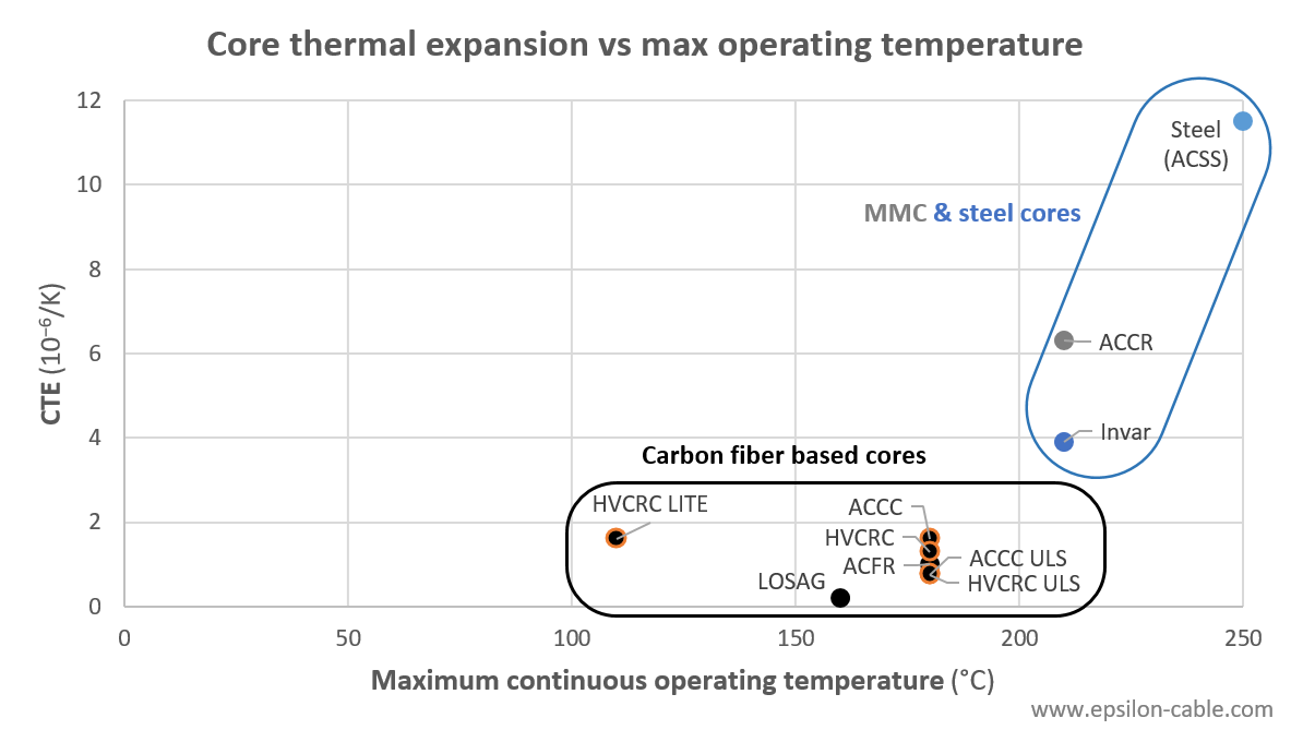
A prime example of how a conductor may not fully take advantage of its core thermal rating is ACSR. Despite having a core capable of operating at more than 200°C, ACSR conductors are limited by the hard-drawn aluminum strands, which would lose mechanical strength when exposed to elevated temperatures. By contrast, ACSS uses annealed aluminum and is designed for high-temperature operation. However, in practice, this temperature capability does not automatically translate into usable ampacity: the steel core still has a high coefficient of thermal expansion, so the conductor may reach its sag or clearance limit before its thermal limit. This makes ACSS a relevant high-temperature metallic conductor, but not really a low-sag solution.
Most carbon-glass composite core conductors, including HVCRC and ACCC, are designed for continuous operation around 180°C and emergency operation around 200°C. This operating range already covers most HTLS reconductoring needs while maintaining a balanced compromise between ampacity, sag control, aging resistance and installation practicality.
ACCR is rated up to 210°C continuously and 240°C in emergency conditions (just like invar), but this comes with much higher material cost, density, thermal expansion and installation risks than carbon-based composite cores.
On the other end of the temperature spectrum, HVCRC LITE conductors offer a cost-effective “Standard Temperature Low Sag” alternative when high temperature operation is not required, which can be interesting to reduce project costs of greenfield projects, and in some cases for reconductoring.
Full-carbon core technologies, such as Lo-Sag type conductors, offer the lowest thermal expansion and the highest specific stiffness.
However, they require careful system-level validation of thermal aging, gas release, galvanic protection and mechanical integrity at elevated temperature, with a thermal limitation at 160°C in most cases.
This does not reduce their relevance for low-sag applications, but it illustrates an important point: the best conductor is not necessarily the one with the highest maximum temperature, but rather the one that combines sufficient temperature capability with low sag, low losses, low weight and long-term reliability.
For this reason, Epsilon’s engineering team is already working on the next generation of HVCRC conductors, with the objective of extending continuous operating temperatures beyond 200°C while preserving the advantages of the hybrid carbon-glass architecture: high tensile strength, low density, very low CTE, integrated galvanic protection and proven installation robustness.
A side note on LITE “Standard-Temperature Low-Sag” conductors:
Not every project requires operation at 180°C or above. For most greenfield lines and some reconductoring projects, the most relevant objective is not maximum temperature, but a better balance between sag, losses, conductor weight and project cost.
This is where standard-temperature low-sag concepts such as HVCRC LITE can be relevant: they have the advantages of composite cores without over-engineering the conductor for extreme thermal operation, offering a much more cost effective option than standard HTLS conductors.
Creep behavior: small strain but significant sag impact for heavy loads
Creep is an important parameter that cannot be fully captured by the core-property charts above.
Long-term elongation depends on the core material, the aluminum layers, the operating temperature, the mechanical loading history and the conductor architecture.
The creep experienced by steel core will induce a significant permanent sag over time, especially for lines with ice loading. A 0.12% creep strain as observed on the curve below may look small, but on a suspended conductor it will have a significant impact. It would for example permanently increase sag by 3 to 4 m on a typical span of 300 to 400 m.
On the other hand, composite cores offer a stable mechanical behavior with an almost negligible creep, which is very clear on creep curves measured under comparable load and temperature conditions:
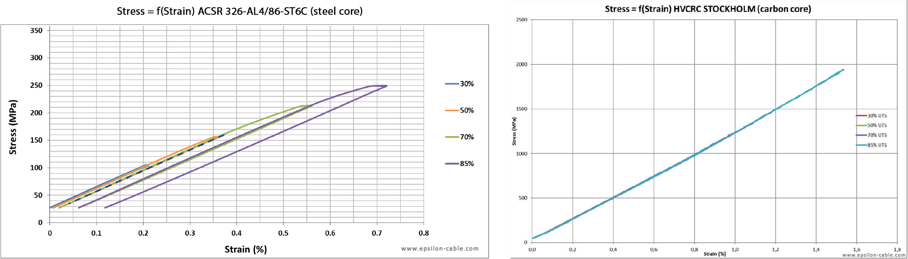
Stress-strain curves for a steel core (left, source: Nexans) and a HVCRC composite core (right, source: Sicame).
Standard hybrid, ULS hybrid and full-carbon cores: three useful performance levels
There are three broad families of carbon-based composite cores, each with distinctive properties.
Standard hybrid carbon-glass composite cores
Standard hybrid carbon-glass cores, such as HVCRC and ACCC, combine carbon fibers, glass fibers and an epoxy matrix in a monolithic composite rod manufactured in one single step thanks to the pultrusion process.
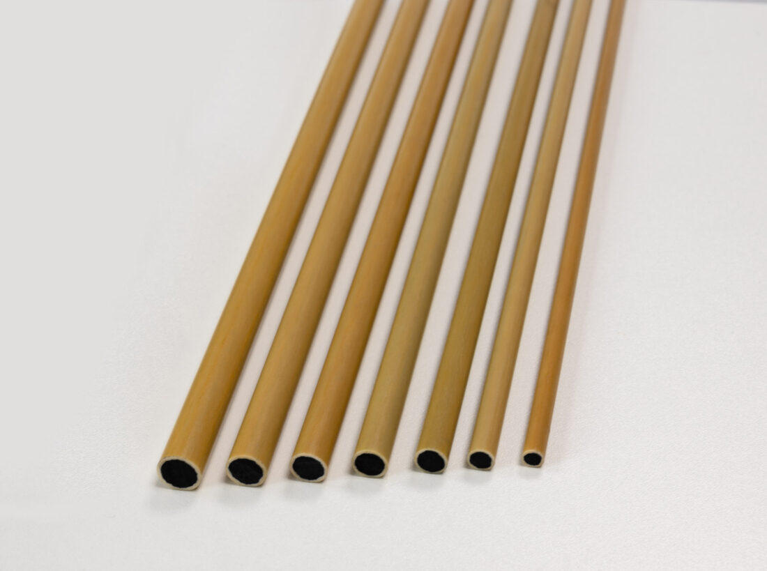
The carbon fibers provide tensile stiffness and strength. The glass fiber layer provides an electrical insulation for galvanic corrosion protection of the aluminum strands, and contributes to mechanical robustness.
This type of hybrid core is ideally suited for most HTLS reconductoring projects, where the objective is to increase line capacity while maintaining low sag, with minimal structure reinforcement.
Its strength is not based on one extreme property, but rather comes from a balanced combination of strength, low density, low CTE and field-proven handling.
Ultra Low Sag hybrid carbon-glass composite cores
Ultra Low Sag (ULS) or Extra High Strength hybrid cores push this hybrid architecture further by using a higher grade of carbon fibers. Compared with standard hybrid carbon-glass cores, HVCRC ULS and ACCC ULS cores provide higher tensile strength, higher elastic modulus and an even lower thermal expansion. This moves the hybrid core closer to full-carbon mechanical performance while keeping the advantages of a hybrid glass-carbon architecture.
For line design, ULS hybrid cores provide a measurable shift in the mechanical and sag performance of the core. They are often used for wide spans and areas with strong ice load requirements.
Full-carbon composite cores
Full-carbon rods used in Lo-Sag type conductor technologies provide the highest specific stiffness and the lowest thermal expansion among all core options. From a material-performance perspective, they represent the upper end of the composite core range.
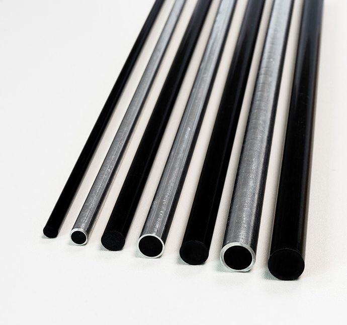
Their extremely low CTE makes them particularly attractive where thermal sag control is critical. Their specific mechanical performance is also very high because they combine high tensile strength, high modulus and low density.
The trade-off is that full-carbon architectures require careful management of system-level design considerations:
- Galvanic behavior: full-carbon cores require an additional protection layer to prevent direct contact between carbon fibers and aluminum strands. This is generally achieved by an aluminum cladding / tubing around the carbon core.
- Handling: higher modulus generally comes with stricter bending-radius requirements during stringing and handling.
- Thermal operation: full-carbon architectures and their protection systems must be validated carefully at elevated operating temperatures. They are generally limited to 160°C for this reason (and any claim of higher operating temperature should be carefully scrutinized to avoid serious issues once the line is energized).
The case of older advanced technologies: ACCR and ACFR
ACCR and ACFR are two earlier advanced conductor technologies based on different design philosophies from modern hybrid carbon-glass and full-carbon rod technologies. They remain in sporadic use, but have lost most of their relevance when compared with more recent and efficient technologies.
ACCR is a metal-matrix composite (MMC) conductor designed by 3M in the late 1990’s. Its alumina fiber and aluminum-matrix composite core has a high elastic modulus and excellent high-temperature capability, but it does not offer the same low density and low CTE combination as carbon-based composite cores, and its cost is by far the highest of all core options.
Its deployment has remained limited due to a well known brittleness issue which makes its installation very challenging. For this reason, the technology has now been sidelined by most utilities.
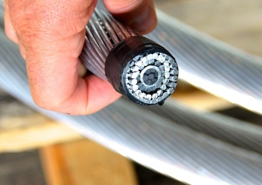
ACFR’s stranded carbon composite core architecture was also designed in the 1990’s in Japan by Tokyo Rope, with its initial application in civil engineering. This architecture improves flexibility and handling tolerance, but significantly reduces axial strength and stiffness when compared with monolithic pultruded rod technologies. After struggling to meet its market for more than 20 years, the technology is now marketed as a niche product focused on flexibility, for projects where this is critical.
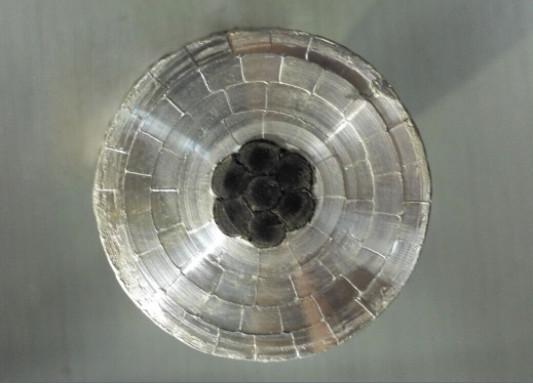
ACCR and ACFR / CFCC are part of the history of advanced conductors and help understand how the market evolved. Multistrand composite cores remain an interesting option for projects where flexibility is paramount, but for today’s comparison, the more relevant question is the difference between hybrid carbon-glass cores and full-carbon cores.
Key takeaways from core-level properties
Core-level charts are useful because they show clear material trends:
- A stiffness vs strength chart shows that carbon-based composite cores provide a higher tensile strength than steel, while steel remains equivalent nor superior in absolute modulus.
- A specific stiffness vs specific strength chart shows the most important lesson: once material density is considered, carbon-based composite cores move into a different performance range from metallic cores, with a ratio between 3-to-1 and 5-to-1
- A CTE chart shows why carbon-based composite cores are so effective for low-sag operation, as their thermal expansion is much lower than steel, invar and metal matrix composites.
Practical implications for grid operators
Obviously, these charts only compare bare cores and are not a complete conductor selection tool.
At conductor level, the final performance depends on:
- how much aluminum is available for current carrying ;
- how much mechanical load is transferred to the core at operating temperature ;
- how the conductor behaves after the knee-point ;
- how creep is managed over time ;
- what operating temperature is allowed continuously and in emergency ;
- installation constraints and hardware compatibility ;
- how sag, losses and structure loads are optimized together ;
This is where conductor engineering begins. Core material properties define the possible performance envelope, but conductor design determines how much of that envelope can be used in the field.
For utilities and transmission engineers, the best core technology is not necessarily the one with the highest modulus, the highest tensile strength or the lowest CTE taken separately: the real value lies in the right combination of those properties.
Carbon-based composite cores are attractive because they combine:
- high tensile strength
- low density
- strong specific mechanical performance
- low thermal expansion
- compatibility with many conductor designs
This combination is particularly relevant for reconductoring projects, where operators need to increase ampacity without rebuilding towers or acquiring new rights of way.
In that context, traditional steel cores and improved metallic cores remain useful reference points. They show what can be achieved by improving conventional materials, but carbon-based composite cores show what becomes possible when the material system itself changes.
Branding note: HVCRC®, ECRC® and CORECHECK® are trademarks of Epsilon Composite SAS, registered in certain jurisdictions. Trademark registrations and commercial designations may vary by country. Products intended for the United States market are marketed and sold under the ECRC® brand, not under the HVCRC® brand.
* Methodological note: With line design and mechanical performance in mind, values in this article are normalized on the full outside-diameter envelope of the core. This allows a direct comparison of how much tensile strength and stiffness each technology delivers within the same conductor-core space.
Equivalent stranded-core values are calculated for a 1+6 strand architecture and expressed against the gross cross-section of a solid rod with the same outside diameter. According to IEC 61089, stranding has a limited impact on the ultimate axial strength of steel cores, because steel wires can redistribute stress before failure. For stranded CFRP cores such as the one used in ACFR conductors, the stranding penalty is more significant: about 16% according to the manufacturer’s data. At equal outside core diameter, this makes ACFR mechanically less efficient than its nominal net-section values may suggest.

About the Author, Alexandre LULL
Alexandre is Managing Director of Epsilon Composite. After studying composite materials, aerospace engineering and business management, he began his career in the Airbus group, before joining Epsilon Composite. He is closely involved in the activities of Epsilon Cable to support the modernisation of electrical infrastructures. As a leader, Alexandre is focused on developing the company’s global performance, integrating extra-financial criteria and sustainable development into its strategy.