


- Home
- > Expert Insight
- > Conductor design
- > Pre-tensioned aluminum-encapsulated carbon cores: does the physics add up? An engineering review of TS Conductor’s AECC pre-tension claim
Pre-tensioned aluminum-encapsulated carbon cores: does the physics add up? An engineering review of TS Conductor’s AECC pre-tension claim
Unidirectional carbon fiber composite cores have become the strength member of choice in advanced overhead conductors, offering exceptional tensile strength, high stiffness, low density, and near-zero thermal expansion compared to steel or aluminum-based cores. These properties translate directly into higher operating temperatures, reduced thermal sag, and increased transmission capacity without requiring structural modifications to existing towers. However, this performance advantage comes with a well-documented materials science trade-off: while unidirectional carbon fiber composites excel in tension, their compressive strength is significantly lower: typically only 60-70% of their tensile capacity. This asymmetry makes the core inherently vulnerable to a specific and often underestimated failure mode: fiber compressive buckling under bending loads.
During installation, handling, or in-service conditions, such as spooling onto a reel, passing over sheave wheels or mechanical mishandling in the field, the carbon core is subjected to localize bending. Any bend imposes a compressive stress on the fibers at the inner radius of the curve, even while the conductor as a whole may be under global tension. If this local compressive stress exceeds the fiber’s compressive strength threshold, the result is not a gradual, visible degradation but a sudden, often internal fiber failure.
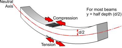
Assessing compression stress during bending is therefore not a secondary design consideration but a foundational requirement for qualifying and safely deploying carbon-core conductors. It directly informs critical parameters such as minimum bend radius, maximum sheave wheel and reel diameters. Understanding and quantifying this behavior allows engineers to define safe handling envelopes, validate compatibility with existing hardware and installation practices, and ultimately prevent premature or catastrophic conductor failure, making it a central pillar of any technical evaluation of unidirectional carbon fiber composite core conductors.
Compression strength, a property affected by different parameters
Before performing any compression stress calculation, it is essential to first assess the compressive resistance of the carbon fiber composite and gain a thorough understanding of the various parameters that influence its ultimate compressive strength:
1) Fiber volume fraction (Vf) and fiber type
As with tensile behavior, compressive resistance is highly dependent on the fiber volume fraction and the type of carbon fiber used. For advanced conductor composite cores, most suppliers rely on the pultrusion process with a Vf of around 70% and high-strength grade fibers. This typically yields ultimate compressive strength values around 1 800 MPa for pultruded profiles reinforced with high-strength carbon fibers.
2) Quality of the pultrusion process
Pultrusion is a complex manufacturing process that requires excellent fiber impregnation by the polymeric matrix, along with a precisely balanced pressure during curing within the die. This process know-how, which remains proprietary to each manufacturer, has a significant impact on the final tensile and compressive properties. If fibers are damaged during impregnation or curing, the strength properties drop drastically, while the modulus of elasticity remains largely unaffected.
3) Fiber misalignment
As with any compressive loading, buckling is the governing failure mechanism, and fiber misalignment significantly amplifies this buckling effect. The work by Waters et al. examines this phenomenon in depth, demonstrating that even a few degrees of fiber misalignment can drastically reduce compressive strength.
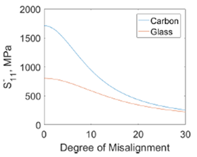
Waters, D. H., Hoffman, J. D., & Kumosa, M. (2021). Effect of fiber misalignment on bending strength of pultruded hybrid polymer matrix composite rods subjected to bending and tension. Composites Part A: Applied Science and Manufacturing, 143, 106287.
Defining the maximum admissible compressive stress: a risk-based assessment
Having identified the key parameters influencing compressive strength, the central question remains: how do we define the maximum admissible compressive stress in the core? A suitable safety margin must be applied to account for raw material variability and manufacturing process tolerances.
At Epsilon, we consider that the compressive stress in the core should not exceed 900 MPa. This corresponds to a safety margin of approximately 50%, consistent with the safety factors applied in overhead line design, where the tensile stress in the conductor never exceeds 50-60% of UTS, even under the most severe load cases such as wind or ice.
This approach forms the basis of our bending rules: 170 × core diameter for standard HVCRC, and 180 × core diameter for HVCRC ULS and Lo Sag cores, which exhibit higher stiffness.
Assessing compression stress during bending
The calculation of compressive and tensile stresses during benging is quite easy:
Where:
σ: stress in the core at the given r
r: core radius
R: bending radius
E: modulus of elasticity.
It is then straightforward to estimate the tensile or compressive stress in any part of the core.
Let’s consider a full carbon core with a diameter of 8.5 mm, bent around a 1500 mm reel, using a full carbon fiber composite with a standard modulus of elasticity of 150 GPa (high-strength carbon fiber, Vf = 70%).
As shown below, we reach 850 MPa in both compression and tension.
What about reducing compressive stress through tensile pre tension?
A solution marketed by a startup has recently gained visibility on the market: TS Conductor claims that its Aluminum Encapsulated Carbon Core (AECC) technology incorporates a pre-tensioned carbon core whose pre-stress is preserved by the aluminum encapsulation, thereby reducing compressive stress during bending and allowing a smaller bending radius than other composite core solutions. Let’s examine the mechanical basis of this claim.
Let’s calculate the benefits of this approach by determining the added tensile strength at three given elongation levels (0.1%, 0.2%, and 0.3%).
The added tensile stress is calculated as follows, for a given elongation ε:
| Elongation for pre stress | Tensile stress |
|---|---|
| 0.1 % | 150 MPa |
| 0.2 % | 300 MPa |
| 0.3 % | 450 MPa |
This overstress at 0.3% elongation effectively reduces the compressive stress down to 400 MPa, while increasing the tensile strength to 1300 MPa.
In other words, a core pre-tensioned to 0.3% elongation could be bent down to a diameter of 950 mm and still exhibit the same compressive stress as a standard core, without pre-tension, spooled on a 1500 mm reel.
| Elongation | Bending diameter |
|---|---|
| 0 % | 1 500 mm |
| 0.1 % | 1 250 mm |
| 0.2 % | 1 100 mm |
| 0.3 % | 950 mm |
However, this clear theoretical benefit has one counterpart regarding conductor design.
Design consequence: a reduced remaining tensile strain margin
Retaining tensile pre-strain in the finished core necessarily reduces the additional tensile strain available before failure. For example, for a composite core with an elongation at break of approximately 2%, a retained tensile pre-strain of 0.3% means that about 15% of the total strain-to-failure range is already present before any additional external tensile load is applied. This does not reduce the intrinsic tensile strength of the composite, but it does reduce the remaining tensile strain margin from the finished pre-stressed state.
However, the AECC conductor datasheet for the pre-tensioned core reports a RTS of 2,750 MPa, well above the other full-carbon-core solutions currently available on the market:
- Nexans Lo Sag: 2,250 MPa min (source)
- De Angeli ACCS: 2,300 MPa
Therefore, the reported RTS of 2,750 MPa is about 20% higher than the values reported for comparable non-pre-tensioned full-carbon-core solutions, despite the claimed retained pre-strain already using part of the remaining tensile strain margin.
This apparent combination of unusually high RTS and meaningful retained pre-strain therefore deserves further clarification.
Besides this design inconsistency, the real challenge for pre-tension of the core lies in manufacturing, specifically, in achieving and maintaining a pre-stressed carbon fiber core encapsulated within an aluminum layer.
Manufacturing: that’s where it gets complicated
During the manufacturing of such a core, combining tension on the core with extrusion of molten aluminum, four challenges appear:
- The temperature during extrusion is quite high, around 500-600°C. These temperatures, well above the thermolysis temperature and glass transition temperature of the polymeric matrix, raise questions about potential degradation of the matrix and reduction of core tensile strength.
- The load necessary to pull the core to the correct elongation, and the consequences in terms of spools and pulling equipment on the line.
- If the carbon fiber composite core is pre-stressed during extrusion and stress released at the end of process, assuming the aluminum encapsulation and composite core remain bonded (cohesive), the aluminum will be put into compression to satisfy equilibrium. The question is whether the aluminum can withstand that level of compressive stress.
- Aluminum’s high coefficient of thermal expansion causes significant shrinkage during cooling at the end of the extrusion process. If the aluminum encapsulation and composite core remain bonded (cohesive), how does this not reduce the pre-stress applied to the core?
We will detail below the different challenges, based on calculations and real cases.
1) 500°C temperature during extrusion
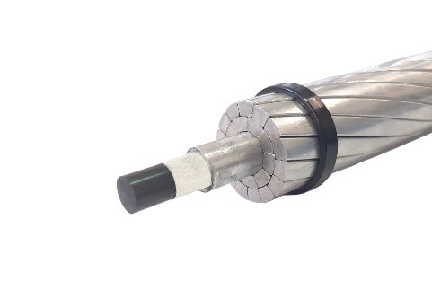
Aluminum extrusion must be performed above 500°C to melt the aluminum. This temperature is well above both the glass transition temperature (Tg) and the thermolysis temperature (T_thermolysis) of the core material: Tg being around 220°C and T_thermolysis around 250°C for this type of product.
Exceeding Tg causes a reversible loss of mechanical properties (approximately 20% in tension and 80% in flexural strength), whereas exceeding T_thermolysis (as defined in IEC 62818-1, determined by Thermogravimetric Analysis) induces irreversible degradation.
To protect the core from extrusion heat, De Angeli Prodotti applies a protective tape.
This constraint requires an extrusion and cooling process fast enough to prevent heat transfer to the core.
2) High loads during extrusion, an impact on equipment
First, we need to consider the minimum tension to be applied to reach the given elongation. Keeping the same example of a 8,5 mm core, we can see below that a tension of at least 2,5 tons needs to be applied during the extrusion process to reach 0,3%.
| Elongation | Stress | Strength |
|---|---|---|
| 0,10% | 150 MPa | 8,5 kN |
| 0,20% | 300 MPa | 17,0 kN |
| 0,30% | 450 MPa | 25,5 kN |
This high level of strength induces significant torque, requiring a strong pulling system and reinforced steel reels capable of carrying these loads.
An effective safety perimeter around the line is also necessary to prevent accidents in the event the core breaks under tension during the extrusion process.
3) Residual compressive stress in the aluminum encapsulation.
Assuming perfect adhesion between the composite core and the aluminum encapsulation, axial force equilibrium requires any residual tensile force in the composite core to be balanced by an equal and opposite force in the aluminum, thereby putting the aluminum encapsulation into compression.
| Aluminum thickness | Aluminum cross section |
|---|---|
| 1 mm | 29,8 mm² |
| 2 mm | 66,0 mm² |
| 3 mm | 108,4 mm² |
Aluminum encapsulation must be a 1XXX series alloy in order to provide electrical conductivity above 60% IACS. However, this type of aluminum has a yield strength of only around 50 MPa. As shown below, even a 3 mm thick layer is unable to withstand the various compressive stresses involved:
| Elongation | Compression load | Compression stress 1 mm thick alu | Compression stress 2 mm thick alu | Compression stress 3 mm thick alu |
|---|---|---|---|---|
| 0,10% | 8,5 kN | 285 MPa | 129 MPa | 79 MPa |
| 0,20% | 17 kN | 570 MPa | 258 MPa | 157 MPa |
| 0,30% | 25,5 kN | 856 MPa | 387 MPa | 236 MPa |
4) Retraction of aluminum during cooling, another evidence that aluminum cannot hold the core in a pre-stressed state
After considering the stress in the aluminum, we need to consider the coefficient of thermal expansion of aluminum: 23 x 10-6.
This important coefficient of thermal expansion implies a retraction during cooling of 1% with the parameters below:
| Parameter | Value |
|---|---|
| Tmax | 500 °C |
| Tmin | 20 °C |
| ΔT | 480 °C |
| Coefficient thermal expansion aluminum | 23 x 10-6 K-1 |
| Length | 1000 mm |
| Length contraction | 11 mm |
| Relative thermal contraction | 1.10% |
If the aluminum encapsulation and composite core remain bonded (cohesive), we can see that such elongation would clearly erase the composite core’s pre-stress: it could even put the composite core into compression.
Conclusion
On paper, a pre-tensioned encapsulated core is an elegant solution: by adding tensile pre-stress to the carbon fiber composite before it is bent, the compressive stress generated during spooling, sheave passage, or handling can be significantly reduced, allowing a smaller bending radius without exceeding the core’s admissible compressive stress.
However, this benefit only holds if the pre-stress is actually preserved once the core is encapsulated, and this is where the concept breaks down. Maintaining the core in a pre-stressed state requires the aluminum layer to carry the equilibrium compressive load, but a 1XXX series aluminum, the only option compatible with the required electrical conductivity above 60% IACS, has a yield strength of only around 50 MPa. As shown, even a 3 mm thick aluminum layer would need to withstand compressive stresses higher than this limit. The aluminum would therefore plasticize well before equilibrium is reached, meaning it cannot hold the core in its intended pre-stressed state.
Even setting aside this compressive limitation, the thermal behavior of aluminum during cooling compounds the problem: the high coefficient of thermal expansion produces a shrinkage in the order of 1% as the assembly cools from extrusion temperature to ambient. If the aluminum and composite core remain bonded, this thermally-induced contraction alone is of the same order of magnitude as the applied pre-tension, and would largely erase it, potentially driving the core into compression rather than preserving the intended tensile pre-stress.
Taken together, these two independent effects indicate that a pre-tensioned, aluminum-encapsulated composite core cannot reliably retain its pre-stress once manufactured, regardless of the tension applied during extrusion. This is consistent with the unexplained RTS value observed on the only pre-tensioned product currently on the market, which is announced 15-20% higher than competing non-pre-tensioned full-carbon cores, rather than lower as pre-tensioning theory would predict.
In conclusion, while the pre-tensioning concept is sound in theory and would bring real operational benefits if achievable, the physics of the aluminum encapsulation process make it, in practice, extremely difficult to manufacture a core that genuinely retains its pre-stress. Until conclusive manufacturing evidence is provided, this solution should be regarded with caution: a seemingly good idea on paper, but a dream in reality.
Print / download the article (pdf)
Edition note, August 10, 2026: Following technical comments from TS Conductor, we reviewed and corrected 2 points in the analysis: the force-balance calculation between the composite core and the aluminum encapsulation, and the interpretation of retained pre-strain in relation to UTS. The corrected calculations and wording do not alter the overall conclusions of the analysis.

About the Author, José PORTOLES
José was the first engineer to join Epsilon Composite after the company was founded by Stéphane Lull in 1987. Over nearly four decades, he has played a key role in the company’s development, becoming a shareholder and one of the composite industry’s leading experts in materials science and applied mechanics.
Known among his colleagues for his remarkable engineering intuition, his trusty 1986 Sharp PC-1403 calculator, his kindness and his unmistakable southern French accent, José currently serves as Director of Materials and Processes. Over the years, he has contributed to the development of most of Epsilon’s high-performance epoxy resin systems and to several of the company’s major innovations and patented technologies, including K1® tubes, the Pullwinding process and CORECHECK®.
Having now passed on most of his knowledge to a new generation of engineers, José is beginning to consider retirement. His colleagues are nevertheless trying to convince him that life without a seemingly impossible technical challenge might quickly become rather dull, and that he should therefore stay with them for a few more years to provide a much-needed dose of common sense in the age of generative AI.
In the meantime, José has agreed to share some of his extensive experience and insights through a series of technical articles on materials science, mechanical engineering and composite manufacturing processes.